CABLE MATERIALS
CABLE MATERIALS
CONDUCTORS AND INSULATORS
We sometimes forget that many cables are not designed to conduct electrical power or signals, such as cables that support bridges, actuate ailerons, and tow cars, for example. Mechanical wire & cable is a big (but another) industry.
There are, however, similarities between mechanical and electrical wire and cable — at least in terms of their means of manufacture.
As strands of wire are made, they are drawn through progressively smaller dies. This is true of all wire. Diamond dies are used, due to their extreme hardness, and the fact that they retain their precision size for a long time. In fact, the American Wire Gauge (AWG) sizing system suggests this drawing procedure. For example, a size 22 AWG wire, smaller than 20 AWG, is drawn, theoretically, through 22 progressively smaller dies. Larger wire is drawn through fewer dies; hence, the lower-number “gauge.” See Table 1.
BARE ANNEALED COPPER
| AWG | Dia (in.) | Circular Mils |
Ohms per 1000 ft. |
Lbs per 1000 ft. |
|---|---|---|---|---|
| 10 | 0.1000 | 10000 | 1.00 | 31.43 |
| 12 | 0.0791 | 6250 | 1.60 | 19.77 |
| 14 | 0.0633 | 4000 | 2.50 | 12.43 |
| 16 | 0.0500 | 2500 | 4.00 | 7.818 |
| 18 | 0.0395 | 1563 | 6.40 | 4.917 |
| 20 | 0.0316 | 1000 | 10.0 | 3.092 |
| 22 | 0.0250 | 625 | 16.0 | 1.945 |
| 24 | 0.0200 | 400 | 25.0 | 1.223 |
| 26 | 0.0158 | 250 | 40.0 | 0.769 |
| 28 | 0.0125 | 156 | 64.0 | 0.484 |
| 30 | 0.0100 | 100 | 100 | 0.304 |
| 32 | 0.0079 | 63 | 160 | 0.191 |
| 34 | 0.0063 | 40 | 250 | 0.120 |
| 36 | 0.0050 | 25 | 400 | 0.076 |
| 38 | 0.0040 | 16 | 640 | 0.048 |
| 40 | 0.0032 | 10 | 1000 | 0.030 |
Table 1. Chart of wire sizes. Circular Mils is the square of the diameter in thousandths, and is useful for comparison of the cross-sectional area of a conductor.
METALS
Copper is regarded as the standard in electrical conductors, second only to silver in conductivity, but far more plentiful and therefore economical.
Because soldering copper can be difficult unless a flux is used (which can leave corrosive residues behind), it is usually tinned or plated if it is intended to be soldered. (This does not preclude the use of flux, but the coating makes soldering easier and affords some protection against corrosion overall.)
Bare copper is perfectly suited for pressure terminations (crimping, etc.) which breakthrough surface oxidation.
Aluminum’s slighter weight would suggest it being favored for the weight-conscious aircraft industry. Its weight is about 1/3 that of copper, and even with its poorer conductivity, it performs better than copper on a per pound basis by a factor of almost 2:1.
So why isn’t aluminum preferred? To start with, the physical attributes of wire are only part of the story. Years ago, when copper was in shorter supply, aluminum was often chosen for residential wiring. What was not fully appreciated at the time was the serious effects of the galvanic reaction between aluminum and the brass or copper fittings or terminals in the presence of moisture. This would develop corrosion which would cause failure at the connection, either in the form of an open circuit or, worse, a high resistance, which spawned many a fire. Aluminum proved to be galvanically too aggressive to be placed in direct contact with copper or brass. [Table 2 lists a selection of metals according to their galvanic ranking.]
| Galvanic Series | |
|---|---|
| LEAST NOBLE, CORRODED | |
| Mg | Magnesium |
| Zn | Zinc |
| Al | Aluminum |
| Cd | Cadmium |
| Fe | Iron |
| Cr | Chromium |
| - | Lead-Tin Alloys |
| Pb | Lead-Tin Alloys |
| Sn | Tin |
| Ni | Nickel |
| - | Brass |
| Cu | Copper |
| - | Bronze |
| - | Silver Solder |
| Ag | Silver |
| Au | Gold |
| Pt | Platinum |
| MOST NOBLE, PROTECTED | |
Table 2. Common metallic elements in their order of galvanic potential. Those closer together on this list will be less likely to attack one another in the presence of an electrolyte than those more widely separated. For practical purposes, any moisture other than distilled water can be considered an electrolyte and will induce corrosion. The element nearer the top will be the one affected.
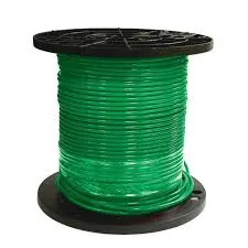
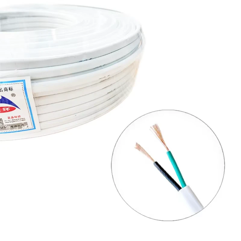
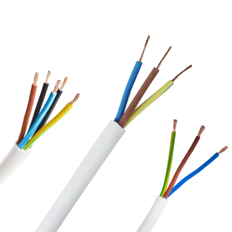
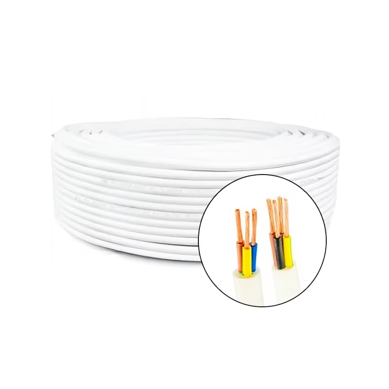
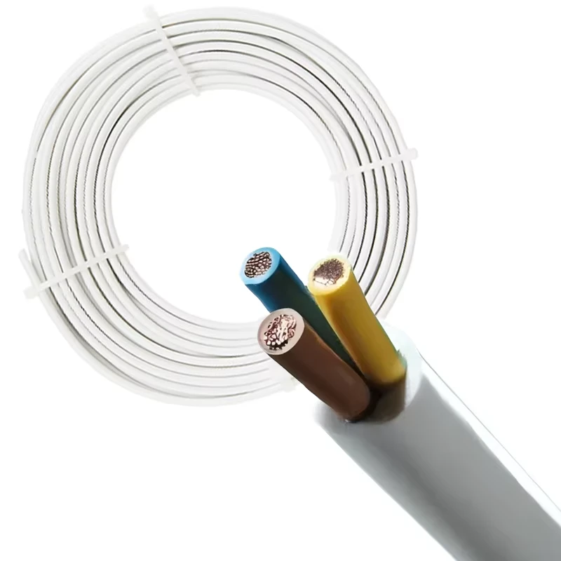
60227 IEC 03 STANDARD 300/500V BV-90 H05V-U NYA SOLID COPPER BUILDING WIRE
The same problem exists in other circuitry. If all terminations were changed to aluminum, the galvanic problem might be solved, but this would apply to all the pins, terminals, contacts, and conducting hardware, and there are a lot of existing systems that would need adaptation. Then, too, aluminum develops a hard layer of oxides on its surface, and this must be penetrated for a good electrical connection.
Although a second-best solution, there are bimetallic (“AL/CU”) adaptors that interface aluminum and copper conductors where re-wiring a home is impractical. These solve the galvanic action problem which compromises fire safety.
One other serious deficiency of aluminum is that it cannot be easily soldered or plated to improve solderability.
All this may suggest there is no legitimate use for aluminum in electrical systems, let alone on aircraft. Not so. In truth, aluminum is approved for airborne use in 6 AWG or larger gauges. This is aimed at power applications, not avionics systems. At the high currents appropriate to large conductors such as these, the effects of possible corrosion are compensated to some extent by the current itself.
Silver conducts better than copper, though it is substantially more expensive. As a result, it is often used as a coating for copper in order to improve skin conductivity and offer some protection against corrosion. This is of particular value at very high frequencies, where the current is more apt to concentrate at the “skin” of the conductor, a phenomenon called skin effect. Silver is also readily soldered.
Tin provides corrosion protection for a copper conductor but does not appreciably affect its conductivity. It is, of course, eminently solderable. A conductor which is “tinned” may actually be coated with a lead-tin alloy — a solder.
Gold, though pricey, is a common plating for brass connector pins, ARINC coax contacts, and parts of some other connectors. Fundamentally, this is the plating of choice because of its excellent corrosion resistance properties in applications where there can be great exposure. Gold is also a good conductor and easily soldered.
Table 3 lists a selection of common conducting materials and their properties, both absolute and relative to copper.
| For 30 AWG Wire | Temperature Coefficient2 | |||||||
|---|---|---|---|---|---|---|---|---|
| Relative Resistance | Ohms per 1000 ft. |
Lbs per 1000 ft. |
“Ohm-Lbs”1 per 1000 ft. |
Melting Point (°C) |
Specific Gravity |
DR per °C | D Length % per °C |
|
| Copper | 1 | 103 | 0.304 | 31.4 | 1083 | 8.89 | 0.0039 | 16.1 |
| Aluminum | 1.64 | 169 | 0.092 | 15.6 | 660 | 2.7 | 0.0039 | 28.7 |
| Silver | 0.94 | 97 | 0.359 | 34.9 | 961 | 10.5 | 0.0038 | 18.8 |
| Gold | 1.42 | 146 | 0.661 | 96.6 | 1063 | 19.32 | 0.0034 | 14.3 |
| Tin | 6.7 | 691 | 0.25 | 172.7 | 232 | 7.3 | 0.0042 | 26.9 |
| RELATIVE TO COPPER | ||||||||
| Copper | 100% | 100% | 100% | 100% | 100% | 100% | 100% | 100% |
| Aluminum | 164% | 164% | 30% | 50% | 61% | 30% | 99% | 178% |
| Silver | 94% | 94% | 118% | 111% | 89% | 118% | 97% | 117% |
| Gold | 142% | 142% | 217% | 308% | 98% | 217% | 87% | 89% |
| Tin | 670% | 670% | 82% | 550% | 21% | 82% | 107% | 167% |
Table 3. A comparison of common conducting materials. 1Ohm-Lbs per 1m ft” is a calculated figure which illustrates the relative weight advantage of each material. This is only for comparison purposes and has no real design purpose. 2Temperature Coefficient is the factor which applies to changes in resistance, or physical dimension for each degree Centigrade. Note the considerable difference in coefficient of expansion between copper and aluminum – yet another reason for their incompatibility. It can be noted that aluminum’s main advantage is weight.
JACKET & DIELECTRIC MATERIALS
INSULATION TEMPERATURE RATINGS
PVC is a poor choice for wire and cable insulation on aircraft — a position affirmed by the FAA. Other good, and approved, choices exist and are readily available.
Temperature ratings reflect the range within which the integrity of the insulation will be maintained — sufficiently flexible when cold and free of the effects of softening or disintegrating at the high end of the scale. It should be noted that the upper-temperature rating should take into account the heat rise caused by power dissipation in the conductor itself.
While most airborne wiring is not expected to endure exposure to the rated temperature extremes, such ratings provide a measure of “headroom” to assure safety in the event of fire or malfunction.
Other insulation properties of concern, depending upon the applications, include the dielectric constant, which dictates loss, mutual capacitance (between conductors), impedance, velocity of propagation, etc. [See The Velocity Factor]
The most prevalent wire & cable insulation materials approved and generally acceptable for aircraft are from the Teflon® family — a familiar brand name for fluoropolymers — which include, for example, PTFE, ETFE (also known as Tefzel®), TFE, and FEP.
MIL-W-22759 wires are TFE- or Tefzel®-insulated. TFE insulation is rated for upper ambient temperatures ranging from +200°C to +260°C, depending on thickness of the insulation and conductor materials. Tefzel® is typically rated at +150°C. Both are suitable to -65°C — which may be realized in proximity to the skin at high altitudes.
TEMPERATURE/PERFORMANCE ISSUES
There are some old “stand-by” coaxial cables — RG58 and RG214, for example — and some newer low-loss cables which can actually cause serious performance problems in avionic systems. Their usefulness is flawed by the use of polyethylene as the dielectric material. This results in a temperature rating of, typically, 85°C (which equals 185°F), which, at first glance, may seem entirely adequate.
But airborne systems are much more safely served by cables with a 200°C rating. Now, 200°C is a whopping 394°F — hot enough to melt solder! Certainly way above human tolerance. So, is it overkill to specify (and pay for) 200°-rated cables? Decidedly not. And here’s why.
Many avionics technicians are aware — from experience, if not by science — that the use of “high-temperature” cables is preferable to the less expensive coaxes. The reason is performance — maybe not at the outset but over time.
In a great many aircraft, cables snake through the airframe in places that can become much hotter than the cabin. Even though contact with or proximity to air ducts, engine firewalls, and other hot spots won’t see temperatures even approaching 200°C, it’s not uncommon for them to experience touch-points well above 100°C. It’s there that the damage can happen. What damage?
A little background: Coaxial cables are, by definition, co-axial — that is to say, the cylinder of shielding and the cross-section of the center conductor share the same axis. The space [dielectric] between them is the same all the way around. Ideally.
Lower temperature dielectric materials soften at relatively low temperatures and inevitably the center conductor migrates off-center, toward the shield, in the direction of gravity or the inside of a bend in the cable. In such a case, the “co-axis” goes off axis, and the concentricity essential to maintaining impedance is impaired. This is permanent and just part of the damage that can happen.
The other part occurs at the box. In the case of a receiver, changes in impedance can cause a reduction in signal — possibly to the point of loss of usefulness.
In the case of a transmitter, things can get worse. The reflection of power [measured as SWR, or Standing Wave Ratio] comes right back to the final stage, producing heat … and heat is the arch-enemy of all electronic components. This is an invitation to the bench for repairs. Do you know someone who would rather pay for repairs than the modest extra cost of a 200°C cable?
Cables using 85°C-rated polyethylene (PE) dielectric materials become soft at temperatures common in isolated spots in aircraft. Some low-loss cables use foamed polyethylene which is soft to begin with. Cable routing with careful attention to avoiding hot spots is important in general, but crucial with such cables.
With so much riding on the integrity of cabling, doesn’t it make sense to always use the better choice?
-
The Quantum Leap of XLPE Cable in Power DistributionNewsMay.29,2025
-
Mastering the Essentials of Building WireNewsMay.29,2025
-
Innovative Horizons of Rubber Trailing CablesNewsMay.29,2025
-
Exploring the Versatile World of Rubber CablesNewsMay.29,2025
-
Decoding the Mysteries of Building CablesNewsMay.29,2025
-
Advancements Redefining Control Cable TechnologyNewsMay.29,2025
-
Why It's Time to Replace Old Rubber CablesNewsMay.28,2025


